The main cause of turbine blade failure is high cycle fatigue. Fatigue
failure is related to repeat cycling of the load on a structural member. The
fatigue life of a structural member i.e. the number of load cycles it can
survive is in general determined by the magnitude of the stress cycles. The
exact relation between the magnitude of the stress and the fatigue life depends
on the material properties of the structural member. In general higher stresses
lead to a shorter fatigue life. For some materials fatigue only occurs if
stresses exceed a certain minimum level for other materials there is no minimal
stress level. If the stresses that are present on the turbine blade during
operation and the material properties of the turbine blade are known then an
estimation of the fatigue life of the turbine blade can be made.

Generally fatigue failure occurs as follows. After a number of load
cycles a crack is initiated. This usually occurs at a point of relatively high
stress concentration i.e. points with sharp geometrical discontinuities or
points with relatively rough or soft surfaces. Once the crack is initiated it
advances incrementally through the material with each stress cycle. In general
this advance is very slow up to a certain point where it accelerates. The final
failure occurs very rapidly. High cycle fatigue corresponds to failure after a
relatively large number of load cycles. High cycle fatigue occurs at stress
levels well below the yield strength of the material where deformation is
elastic. The failure of a structural member is not caused by excessive loading
but by the repeated cycling of the load.
Another cause of static stress failure of blades is blade overheating
related to the departures from normal operating conditions. Such failures are
detected by metallographic methods based on metal structural variations throughout
the entire blade section or in its separate regions as well as on the formation
of thick de-alloyed surface layers. Thus, cracks on ZhS6K-alloy guide blade
edges were discovered after GT adjustment testing for 103 h. with 57 start-ups.
Coating cracking is induced by a local corrosion failure of blade base
metal under the coating. A method for testing small-size coating specimens has
been developed. The method makes it possible to observe strain relief
characteristics during testing and to study the mechanisms of crack initiation
and propagation in a coating up to specimen failure. A series of thermal
fatigue tests was performed using different super alloy specimens with
different coatings. The mechanisms of micro-crack initiation and suppression in
multi-layer coatings have been determined.
LIFE PREDICTION UNDER CREEP & FATIGUE LOAD
The life prediction, more generally
the evaluation of the behaviour of a rupture mechanism, or several mechanisms
at the same time, is a significant task in order to ensure the reliability of
the system. The cycle is non reversible to deal with the mean stress;
equivalent reversible stress is calculated with the
Goodman rule .
Life prediction for fatigue (Nf):
Nf
is defined in this work by the Manson Coffin formulation. Manson Coffin
established that the alternative strain is related to the number of stress
cycles to rupture, by the equation:

E is the elasticity modulus, σf material strength, and b
and c for the majority of materials
are equal to -0.12 and - 0.6.
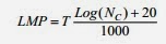
Life prediction for creep (Nc):
Creep for metal is described by the
Larson Miller parameter (LMP). T is the temperature in K degrees; Nc
is the time to creep rupture in hours. The LMP C coefficient is taken equal to
20.
Model for fatigue-creep interaction:
Many approaches have been developed
these last years to predict the safe life of materials subjected to high
temperatures. To consider the interaction between fatigue and creep damage,
several rules of damage accumulation could be used. This accumulation can be
considered as linear or non linear. In this work two damage accumulation models
are used: the linear Miner rule eq. and the non linear Chaboche rule.

It is considered that during a cycle,
the damage of creep passes from the damage D0 to D1 and that the fatigue damage
increases at the end of the cycle from D1 to D2. Two equations and give
respectively the creep and fatigue interactive damage for one cycle:

The coefficients α, β and k are the
material data, defined experimentally. In the two cases, the damage is complete
when damage accumulation reaches the unity. Then the rupture becomes certain.
We can then predict the number of cycles to failure when:

No comments:
Post a Comment