Metal cutting fluid is utilized as a part of metalworking
and machining for various purposes, mostly as a lubricant and for cooling. It
comes in the different type of forms including synthetic fluids, semi-synthetic
fluids, oils and solvent oils.
Synthetic fluids are made of alkaline mixes and compounds
that avert erosion. They are utilized as a part of weakened water and are the
critical part of cooling. Semi-synthetic fluids are a blend of soluble oils and
manufactured fluids and its attributes show up in the two constituents.
Undiluted Oils are used only when making cutting fluids.
They offer the best friction yet bad cooling. Solvent oils are solute with
water and give great lubrication and cooling contrasted with alternate items.
They are the most cost-effective and are hence are very popular among the heavy
metal cutting industry.
In order to select the best oil, you need to gather some
basic information relevant to the selection criteria. For purposes of
simplicity, you need to know the metals in use, the predominant machining
operations, basic machine types, tooling specifics, plant processes and
chemical restrictions for your facility.
Metals
Some metals are more difficult to machine than others.
Stainless steel, exotic alloys and very hard metals demand a very high level of
performance from the cutting oil. Other metals, like brass and aluminum, are
easy to machine with general-purpose oils.
Where tough, low-machinability metals are involved, you will
need highly additized cutting oil with excellent extreme-pressure (EP) and
anti-weld capability. Most often, these oils contain active sulfur and chlorine
to protect the tooling and ensure good parts finish.
For brass, aluminum, many carbon steels and low-alloy
steels, a cutting oil with lubricity additives, friction modifiers and mild
EP/anti-weld performance is sufficient. These oils are generally formulated
with sulfurized fat (inactive) and/or chlorinated paraffin. Active cutting oils
(containing active sulfur) should not be used for brass and aluminum, as they
will stain or tarnish the finished parts. Oils formulated for brass and
aluminum are often called "non-staining" oils.
Machining Operations
Easy machining operations (turning, forming, drilling,
milling, etc.) can be performed at higher speeds and require high levels of
cooling with only modest EP capability. The milder operations can be performed
with lower viscosity, lightly additized fluids.
Difficult machining operations must be run at lower speeds
and require a great deal of anti-weld protection. Oils designed specifically
for the most difficult operations, like thread-cutting or broaching, are
generally higher in viscosity and loaded with EP additives like active sulfur
and chlorine.
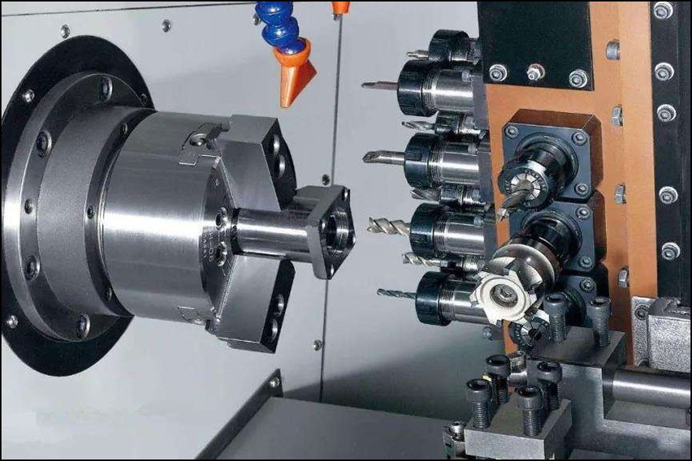
Basic Machine Types
The type of machinery will also dictate some of the cutting
oil characteristics. For example, screw machines experience heavy
cross-contamination between the lube oil and cutting oil. For this reason,
these machines frequently run on dual-purpose or tri-purpose oils that can be
used in the lube boxes, hydraulics and cutting oil sumps.
Grinders, gun drills and deep-hole drilling machines require
lighter viscosity oils for high rates of cooling, good chip and swarf flushing,
through-the-tool delivery and high-pressure application without foaming. CNC
OEMs may place restrictions on the cutting oil due to potential incompatibility
between the cutting fluid and machine components, such as seals. Centerless
grinders may require a tougher fluid than surface grinders.
Qualities and
Functions of a Good Metal Cutting Fluid:
· The principle trademark is its ability to keep
the metal and apparatus temperature stable to abstain from obliterating the
metal because of high temperatures or even a fire on nearby materials.
·
It ought to give appropriate lubrication to
boost the life cycle of the cutting tip and lessen the amount of heat created
by reducing contact.
·
It ought to have the ability to stop rust from
getting on the metal cutters and important metal parts.
·
The cutting fluid must be safe to operate and
also environmental friendly to discard.
·
Fluid should be able to wash out bits of metal
away from the cutting area.
·
The diverse metal cutting fluids require
distinctive application techniques; these incorporate brushing, flooding,
spraying, misting, and dripping. The most widely recognized and used technique
is a Jet method in which liquid is being sprayed to the cutting workpieces.
Non-Cutting Functions
· The selection of a fluid/coolant should also
consider its effect, not just on the part being ground or machined or however
upon the nearby condition of the operation. These contemplations would
incorporate the:
·
Addition of rust inhibitors to control
consumption
·
Stink (scent) protection from keeping the
development of poisonous vapor
·
Adhesive resistance to prevent waste formation
on the finishing product
·
Operator health and nature-friendly
·
Disposability which, contingent upon synthetic
substance, may go under certain ecological restrictions
Cutting Fluid
Maintenance
Cutting fluids lose its quality after some time because of
oil system contamination. Most common type of degradation in the form of tramp
oil, otherwise called sump oil, which is undesirable oil that has blended with
cutting fluid. It begins as grease oil that leaks out from the sideways and
washes into the coolant blend, as the protection film with which a steel
provider coats their items to avert rusting, or as pressure driven oil spills.
Skimmers are utilized to isolate the tramp oil from the
coolant. These are typically slowly rotating vertical disks that are partially
submerged beneath the coolant level in the primary supply. As the disk turns
the tramp oil sticks to each side of the plate to be scratched off by two
wipers previously the plate goes back through the coolant. The wipers are a
channel that at that point diverts the tramp oil to a holder where it is
gathered for waste disposal. Floating waste is additionally utilized as a part
of these situations where temperature or the amount of oil in the water becomes
too much.
Support and checking of the fluids are essential for helpful
fluid life. Some portion of this is in the care and tidiness of the machine
apparatuses themselves. Monitoring involves health and safety checks utilizing
the proper test, including:
·
Refractometers, which are utilized to decide the
aggregate sum of soluble in a solution.
·
Tests for PH levels and alkalinity (corrosive
parts) are additionally valuable.
·
Titration Kits, who are utilized to break down
fluid concentration in metal-cutting fluids sullied with tramp oils.